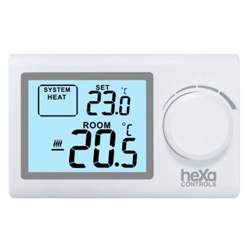
In order to select the valve capacity and diameter, you will need to enter the data in the green fields in the table below.
If the temperature difference (°C) and pressure drop (kPA) data requested from you from the data in the system are not known, the values you need to get should be as follows.
The data to be used in the heating system: temperature difference 20, pressure drop 10 should be taken.
The data to be used in the cooling system: temperature difference 5, pressure drop 20 should be taken.
The results obtained in the valve calculations are given in the red sections in the table.
The most important value given in this section is the Kvs value.
Which brand or model valve to use should be decided according to this data.
Valve with a value below the obtained Kvs value should not be used.
It is normal for the valve you will use to be one or a maximum of two sizes smaller than the installation pipe diameter.
We recommend that you be careful not to use a large valve body or a valve body with a diameter smaller than 2 sizes.
Based on what data do you want to choose?
 |
Choosing the Right Motorized Valve in HVAC
Applications In HVAC installations, motorized valves are one of the most important equipment in fluid and ambient temperature conditioning. In addition to the main purpose, nowadays motorized valves have additional functions in line with the demands of the market and competition. These are the control of other important f(dP,Q) differential pressure and flow control functions in ensuring the temperature comfort condition. In this article, we will consider the selection and control parameters of motorized valves that operate solely on the temperature function. Motorized control valves are classified in more than one category according to engine operating principles, port numbers and task differences. Let's get to know the motorized control valves used in the HVAC installation. Motorized control valves have different characteristics for optimum heat transfer in the installation group, according to port number and duty difference:
2 and 3 Way Motorized Control Valves
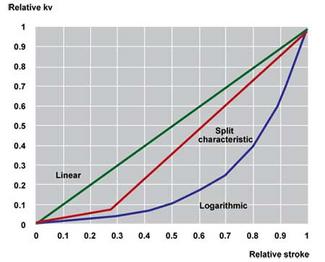
Linear Characteristic
Logarithmic Characteristic
Split Characteristic
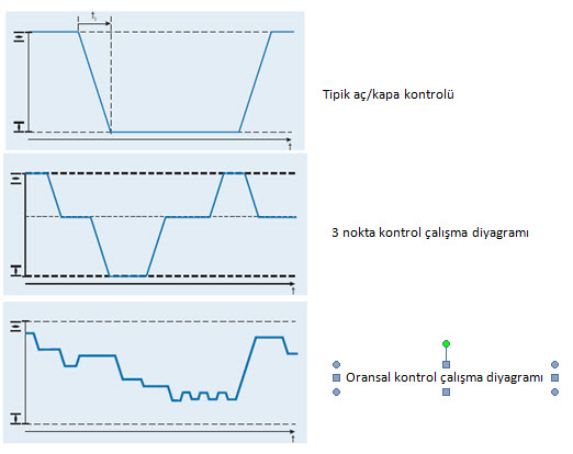
Motorized Control Valves are divided into three groups according to their control principles:
On-Off Control (2 point control)
Floating Control (3 point control)
Proportional Control
Basic Motorized Valve Working Principle
Let's consider the motorized control valve system diagram with an example of a heating system that is frequently encountered in the application area:
The scheme is presented as a typical residential heating installation. When examined, our system consists of two circuits, primary (heating circuit) and secondary (heated circuit) circuit. The heat exchanger separating the two systems from each other provides the desired temperature set value on the secondary side with the motorized control valve on the primary side. In other words, the desired result in the secondary circuit is realized by the control of the primary side. The control of the motorized valve is provided by the electronic controller (PI) in the system. The system ensures that the Y signal action is transmitted to the motorized valve by reasoning of two temperature TSP and T22 inputs.
Valve Control Characteristics
The valve characteristic expresses the relationship between the valve stroke control (opening) of the valve under constant pressure and the flow rate passed by the valve. These provide variation in characteristic as they are classified as linear, logarithmic, split.
The main purpose of the logarithmic characteristic motorized valves, which are mostly used in the sector, is to take the heat transfer control of the logarithmic character heat terminal units under linear control. Namely:
Valve Control Theory
The definition that appears in the selection of motorized control valves is the Kvs value. Let's take a closer look at the functions that the Kvs value, which is the only criterion in motorized valve capacity, depends on. Kv represents the valve capacity in any case at the relevant differential pressure and flow rate.
As can be seen from the formula, line diameter and flow rate are not the only parameters in valve capacitance.
Capacity is a function of flow and differential pressure across the valve.
In order to ensure that the valve motor can control the relevant differential pressure on the valve, it is necessary to check the maximum operating differential pressure operating condition of the actuator of the relevant diameter.
Valve Authority
Valve authority (pressure authority) is a unitless term that expresses the ratio of the entire pressure loss in the installation where it is located. The valve authority corresponds to the ratio of the minimum pressure loss (valve fully open position) to the maximum pressure loss (valve fully closed position). If the valve authority is higher than the relevant values, more precise temperature control is allowed as the valve will be more stable.
- More than 30% should be preferred for 3-way valves.
- 2 yollu vanalar için % 50’den büyük tercih edilmelidir.
More than 50% should be preferred for 2-way valves. The task of the valve actuators is to bring the valve stroke opening to the desired range without any problems with the signal it receives from the controller. Actuators are divided into three according to their control types:
- On-Off Control
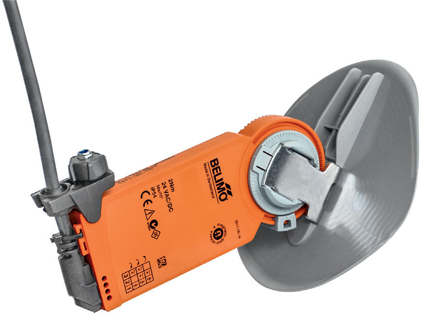
Open and Close motorized valves are used to ensure or stop the flow of fluid without regulating between two points in its stroke. It is used to close and separate the system in open or closed installations.
- 3 Point Control
It provides the desired position with the control of the valve shaft with the open, close or stop signals coming from the system for the entire valve stroke range. It is used in installations requiring less sensitive regulation. Boiler installations can be given as an example.
- Proportional Control
It is the most common application used in sensitive closed circuit installations. The control signal is transmitted from the electronic group as 0(4)…20 mA or 0(2) … 10 V. The valve actuator provides control at very short intervals. This method, which provides the most precise control even at low flows, guarantees optimal control in multi-variable fluid conditions. Sensitive air-conditioning - humidity plants and chiller groups can be given as examples.
In summary, the most important parameter in motorized control valve selection is to determine the valve body capacity at the place of use. Subsequently, it should be ensured that the valve authority has reached the appropriate % authority range in the installation. Differential pressure closing pressure should be checked in dP corresponding to the relevant Kvs value of the manufacturer's valve actuator. Finally, in actuator control, the most suitable one should be selected from three different control principles, depending on the application area and system sensitivity.


